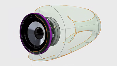
SolidWorks 301: Advanced Surfacing Techniques
/Download all 39 training videos (in MP4 format) plus extra files and resources for a single, one-time fee.
- No memberships.
- No recurring payments.
- Download and keep forever.
- View on any device, any time.
- No ads. No spam. No bloatware.
Sharpen those chopsticks! In this SolidWorks 301 Training Series industrial designer Adam O’Hern continues to elevate SolidWorks ninjas to triple-kickflip-off-the-wall skills with even more real-world design techniques inspired by real-world processes. Whether you’re an aspiring design rockstar or an above-average Maker, here is yet another cadjunkie SolidWorks course that empowers product designers of all kinds to use SolidWorks as a powerful creative tool.
More Righteousness Than You Can Shake a Cheesestick At
In the previous SolidWorks courses, we focused on both the building blocks of a well-organized workflow as well as using that knowledge as a springboard for designing quickly and iteratively. In this series we’ll continue our focus on designing iteratively like we did in the SolidWorks 201 Remote Control series, but with a magnified focus on working with the internal components of our assembly.
Contents
Part 1: Getting Started
In this section, we'll do a quick review of the best practices for setting up our file as well as take a look at gathering assets from other sources (like GrabCAD) that can be used in our final assembly.
- Overview & Collectiong Resources (03:40)
- Document Templates (04:13)
- Document Setup (04:59)
Part 2: Expressing Design Intent
In this section we'll be aligning our gathered resources to start our process of creating an exterior housing. Along the way, we'll take a look at some material settings that will make it easier for us to tell the difference between various components in our assembly.
- Align Transducer (02:17)
- Revolved Body (03:41)
- Material Presets (02:35)
Part 3: Iterative Designing Techniques
In the last section we created what our main housing body...and in this section we'll work on the supplementary components that will help support it. Particularly, we'll be taking a look at creating expressive, organic surfaces using the Spline Tool that we can then use to create solid bodies from. Sweet!
- Base Surfaces (03:54)
- Transistion Surface I (05:04)
- Transistion Surface II (04:21)
- Face Curves (03:37)
Part 4: Working with Constraints: Build the Bracket
While it's easy to design what we want the exterior of our product to look like, it's a bit more of a challenge to ensure that all of the internal pieces will fit together...especially when we're working with pre-existing dimensions. In this section, we'll take a look at how to go about this process more accurately and easily.
- Bracket I (05:21)
- Bracket II (05:30)
- Bracket III (04:36)
- Bracket IV (03:10)
- Bracket V (03:10)
Part 5: Build Out the Body
Now that we have more confidence that our internal components will happily fit within our original housing design, it's time to work on the details of that design. In this section we'll take a look at 'cleaning up' our design and making sure everything both looks aesthetically pleasing and properly fits.
- Base (05:17)
- Leg I (06:08)
- Leg II (03:35)
- Top Housing (06:23)
- Nose Cone (04:58)
- Rear Nose (06:59)
Part 6: Designing Within an Existing Body
While we spent some time making sure that our internal components would match up, we still need to go in and finalize the internal components of our design. In this section we'll take a look at accurately lining up internal components for finalizing their design and placement.
- Port (06:59)
- Assembly Materials (04:00)
- Sensors (08:42)
Part 7: Attach Body Components
Earlier we took a look at how the components of our assembly will meet up together, but we didn't mechanically fit them together. In this section, we'll take a look at creating screw threads as well as other ways of matching up bodies so that they fit together in the real world.
- Threaded Stem I (05:18)
- Threaded Stem II (04:19)
- Threaded Stem III (04:37)
- Leg to Body (04:39)
Part 8: Finalizing Internal Component Design
Phew! Almost there kids! In this section we're going to continue to make sure that all of our components are lined up fitting properly by accurately reviewing what we have done up until this point as well as finalize any last adjustments before moving to the final stages of our design.
- Rear Nose Mount (04:26)
- Bracket VI (04:46)
- Bracket VII (07:48)
- Port Flange (04:16)
- Cable Path (04:16)
- Foot (04:38)
Part 9: Routing Wires and Cables
In this section we'll take a look at how to route electronic wiring and any other cables through an existing assembly design. By the end of this part, you'll have a design that's ready to be plugged in and powered up!
- Center Cable (05:52)
- Cable Coil (05:33)
- Cable Coil (02:27)
- Cable Leads (04:52)
Part 10: Adding Graphic Design and Finishing Touches
In our final section we'll take a look at adding graphic details to your model as well as add any other finishing touches that might need to be done.
- Decal (05:28)
Topics
Overall
Material Presets
Importing Existing Files
Saving Externally
Adding Graphics
Threaded Components
Document Setup
Setup Axes
Customizing Document
Save a Document Template
Assembly Organization
Importing Assets
Sourcing Models
Dimension Assets
Sketch Backgrounds
Aligning Components
Working with Splines
Create a Spline
Relocating Points
Curvature Combs
Pierce Relations
3D Space
Transition Surfaces
Curvatures
Draft Angles
Intersection Curves
Boundary Surfaces
Zebra Stripes
Face Curves
Mates
Mate Relationships
Axial Positions
New + Existing Assemblies
Fix and Float
Assign Materials
Surfaces
Knit Surface
Thicken Surface
Planar Surfaces
Surface Cuts
Internal Components
Extrude and Offset Surfaces
Shell
Lip/Groove Tool
Cable Pathways
Electrical Wires


